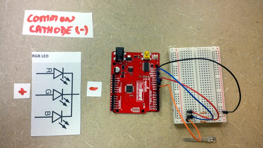

- #CONTROLLING COMMON CATHODE LED WITH ARDUINO HOW TO#
- #CONTROLLING COMMON CATHODE LED WITH ARDUINO CODE#
If your LED has a Vf of 2.0V (green or yellow) that's about 200 ohms. You pick RXi to yield the peak current of 14.3mA, so about (4.8V-Vf)/0.0143. You would pick RSi to yield about 1/20 of the 100mA total LED current through the transistor base, so about 5mA. With this circuit you are driving the entire display current through the MCU ground pin so you are limited to an absolute maximum of 200mA, and you should stay well away from that, so let's assume 100mA total current (meaning an average LED current per LED of only 3.6mA and a peak LED current of 14.3mA) Simulate this circuit – Schematic created using CircuitLab With this value we will be able to choose the corresponding color for the RGB LED.The easiest way to drive this multiplexed display is like this (although the designation is K, what you have is driven the same as a 4-digit common Anode numerical LED display): Note: in programming we usually start to count from 0, not 1. īecause we want to choose between 7 different options, we use the map() function to transform this value from the range 0-1023 to the range 0-6. In the void loop(), we first read the potentiometer’s value with analogRead(). Read potentiometer and choose a mode void loop() By calling this function, instead of 3 redundant lines, you just have one line, which is digitalWriteRGB() with 3 parameters.
#CONTROLLING COMMON CATHODE LED WITH ARDUINO CODE#
This function will help us reduce the code we write in the following.Įvery time you need to change the color of the RGB LED, you will need to call digitalWrite() 3 times. digitalWriteRGB() function void digitalWriteRGB(byte red, byte blue, byte green) Nothing to do for the potentiometer, as an analog pin is already in input mode by default. In the void setup(), we initialize all LEDs (in fact, the 3 legs of the RGB LED) to OUTPUT mode. One for the potentiometer, and one for each color of the LED – we write the code as if we were controlling 3 different LEDs.

Setup RGB and potentiometer pins #define RGB_RED_PIN 11Īt first, as a best practice, we create a define for each pin we are going to use. Int mode = map(potentiometerValue, 0, 1023, 0, 6) Int potentiometerValue = analogRead(POTENTIOMETER_PIN) Void digitalWriteRGB(byte red, byte blue, byte green) We are going to use digitalWrite() – LED fully powered on/off, which means that we have a combination of 7 colors: You can see the RGB LED as a combination of 3 different LEDs that you control separately. In this first application, we are going to modify the color of the RGB LED when we turn the potentiometer knob.
#CONTROLLING COMMON CATHODE LED WITH ARDUINO HOW TO#
How to find out? Simply check the manual or description of what you’ve bought. Depending on your RGB LED, this can be a cathode or an anode. Make a common ground by connecting a GND pin of the Arduino, to the “minus” line of the breadboard.You are learning how to use Arduino to build your own projects?Ĭheck out Arduino For Beginners and learn step by step. Arduino board – I use Arduino Uno, but any board where you have at least 3 PWM compatible digital pins, and one analog pin, is fine.Going further with the potentiometer and RGB LEDĪrduino circuit with RGB LED and potentiometer.Select a different color for each value.Control the RGB LED with potentiometer – analogWrite() – 1536 colors.Power on the RGB LED depending on the potentiometer’s value.Control the RGB LED with the potentiometer – digitalWrite() – 7 colors.Arduino circuit with RGB LED and potentiometer.


 0 kommentar(er)
